In our last soldering article, we wrote about some details about the materials used in soldering as a conceptual introduction to how soldering is done and when to choose different materials or tools. Here, we will cover a more practical side to soldering, showing how some common types of parts might be put together. Keep reading to learn more about practical soldering.
Tool of Choice
In this session, I will be working with a temperature-controlled soldering iron with a mid-size chisel tip and a hot air rework station. With the heat sources, we’ll be using 0.8mm 99.3% tin and 0.7% copper solder with a flux rosin core and flux paste in a syringe, which is both lead-free. I use a brass sponge and tip tinner to keep the special material on the tip of the iron clean and free from oxides. I have a spool of solder wick and a solder vacuum pump to correct any mistakes that might occur, and safety glasses and a fume extractor fan for safety. I keep non-ferrous tweezers, normally closed forceps, and pliers to manipulate parts, and I use either a vice, clamp or 3rd hand tools to hold the part being assembled in place.
Heat
All solder types have their own melting temperature, but if you simply set your iron temperature to the melting point of your solder, you’ll find the bonds lack a clean-looking quality. A more ideal method is to raise the temperature of the iron a bit to compensate for the fact that the iron energy will transfer to the solder and solder joint, lowering the iron temperature. Increasing the iron temperature a bit ensures that the iron has some extra buffer heat energy so that the user can quickly melt solder for multiple solder joints in a row without falling below the solder melting point. The higher temperature also allows the liquid solder to “wet” the electrical contacts better. This soldering iron and hot air rework station recommend setting the iron to about 270F above the advertised solder melting point to ensure the iron is hot enough for smooth ironing but not so hot that you easily burn parts. This iron is set to 698F since my solder melts at around 428F. This solder station’s hot air source has variable temperature and airflow, which can require more tweaking to find the best temperature and airflow setting for the user.
Both the iron and the hot air source have swappable tips to better apply heat for various situations. The iron often comes with different shaped and sized tips. Bigger tips allow more heat transfer through more surface area, but smaller tips can be easier for dealing with smaller parts. Hot-air rework attachments on the other hand mainly change the shape and size of the resulting air jet.
Procedure
Generally, the workflow is, apply flux to the parts, clean the tip of the iron using a wet or brass sponge and if the tip is clean add a small amount of solder to “tin” the tip. This small amount of solder can make it easier to establish good heat conduction between the iron and the components. Press the iron to the solder pad and component lead, vaporizing the flux and cleaning the metal contacts. Press solder wire into the solder pad and contact lead and iron tip to get the solder melting. Add just enough solder to cover the electrical contact surfaces. When the iron tip develops black oxides, clean it with a wet or brass sponge, and if the tip gets very dirty, dipping the hot iron tip into a tip tinner compound, which can rejuvenate the iron surface and make melting the solder easier. This set of steps flux, clean, iron, solder are repeated for any parts being soldered to a PCB, though because many parts have different physical forms, it can be advantageous to strategize how to approach soldering certain parts.
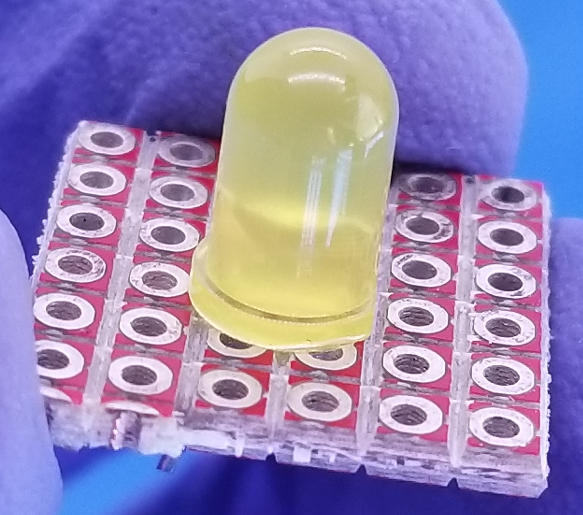
Most two-pin through-hole components can be soldered just like LEDs or resistors. Simply thread the component leads through its designated solder pad hole on a PCB until flush with the board surface and the leads can be bent on the other side of the PCB to hold the component in place. Using this method, an assembler can position many parts in a row without them moving so that they can apply solder to all of the electrical contacts rapidly without having to pick up and put down the iron as many times.
In the photo below an LED is placed into position and leads bent to lock it into place.
 Then a small brush is used to apply flux paste to the metallic contacts that will receive solder.
Then the iron tip is pressed firmly into the metal, followed by the solder which then melts and the capillary effect pulls the molten solder into the solder joint.
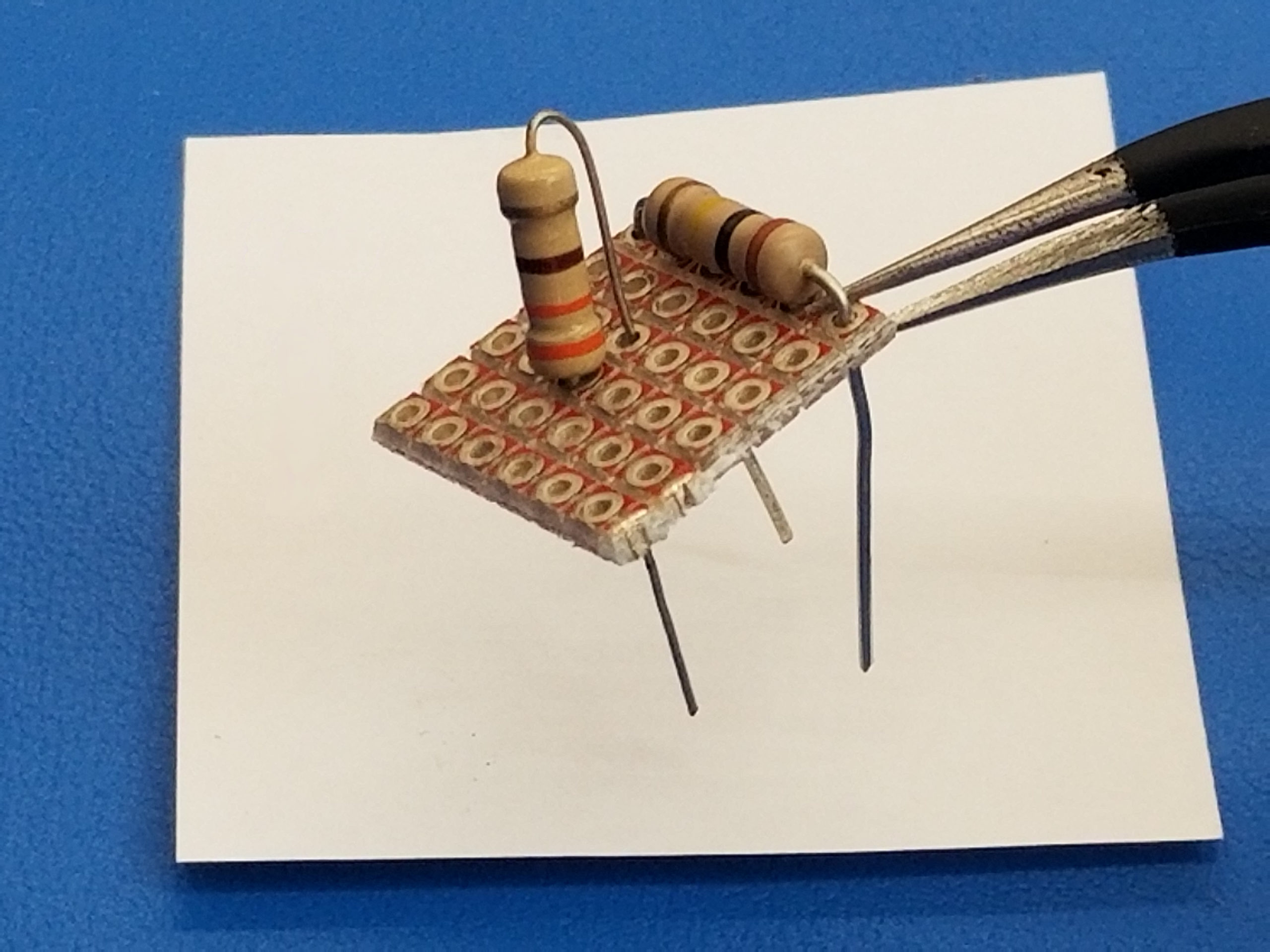
Some components like resistors come in axial packages meaning that they have a long body and electrical leads coming out at each end making a straight line. When placing components onto a PCB design the long body of an axial component can be unfavorable since it takes up a lot of PCB surface area. The leads of these components can be bent into a “vertical” mounting orientation to save on space.
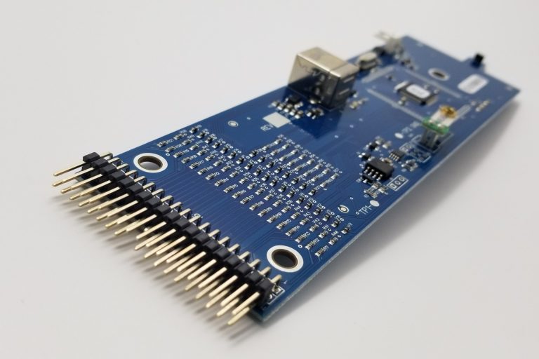
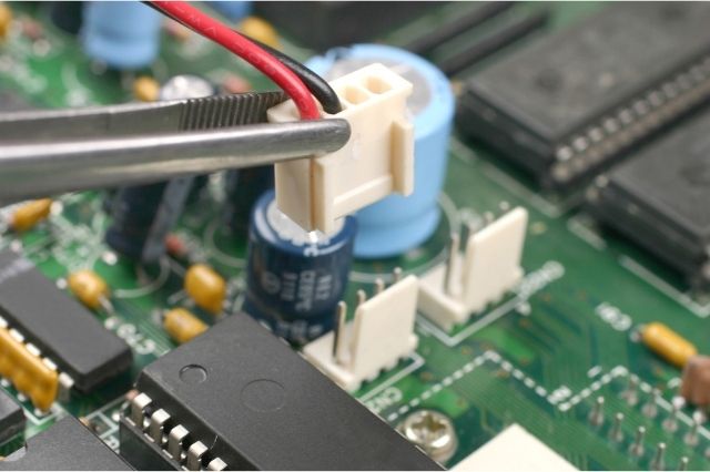
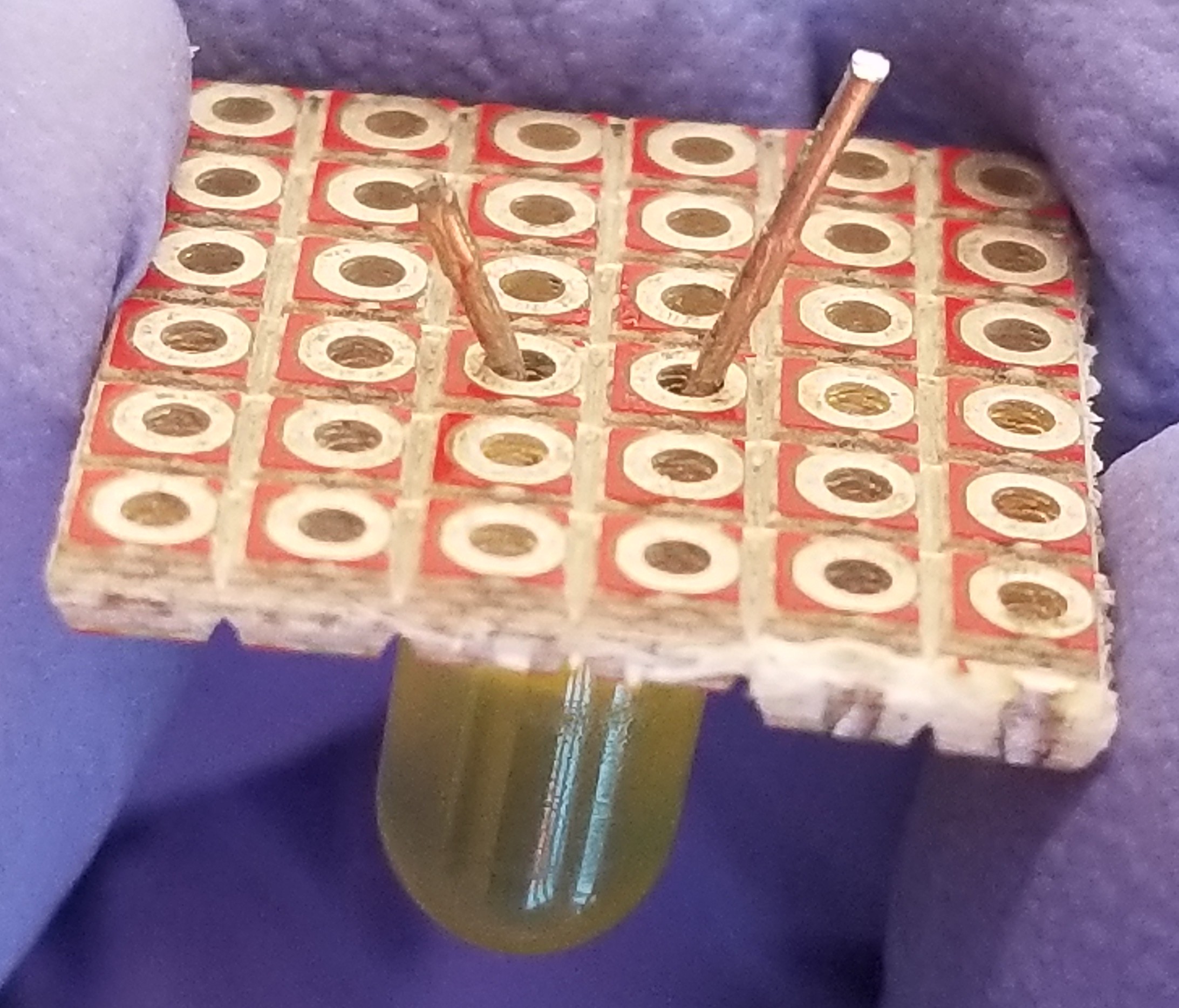
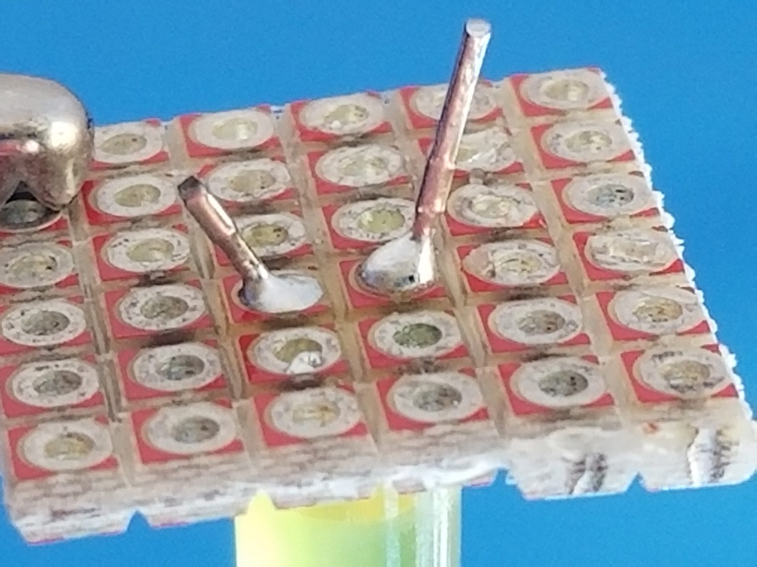
Headers are a useful component for creating a simple way to electrically interact with the device being assembled. The problem is that it can be tricky to hold a header perpendicular to the PCB if you’re holding the iron in one hand and the wire solder in the other.
A way to make sure the part attaches at a right angle is to add a small amount of solder to one hole with no component in it.
Then while holding the iron to the solder pad of that hole insert the header pin through and position it with the solder melted. Pull the iron away and let the solder harden and hold the header in position.
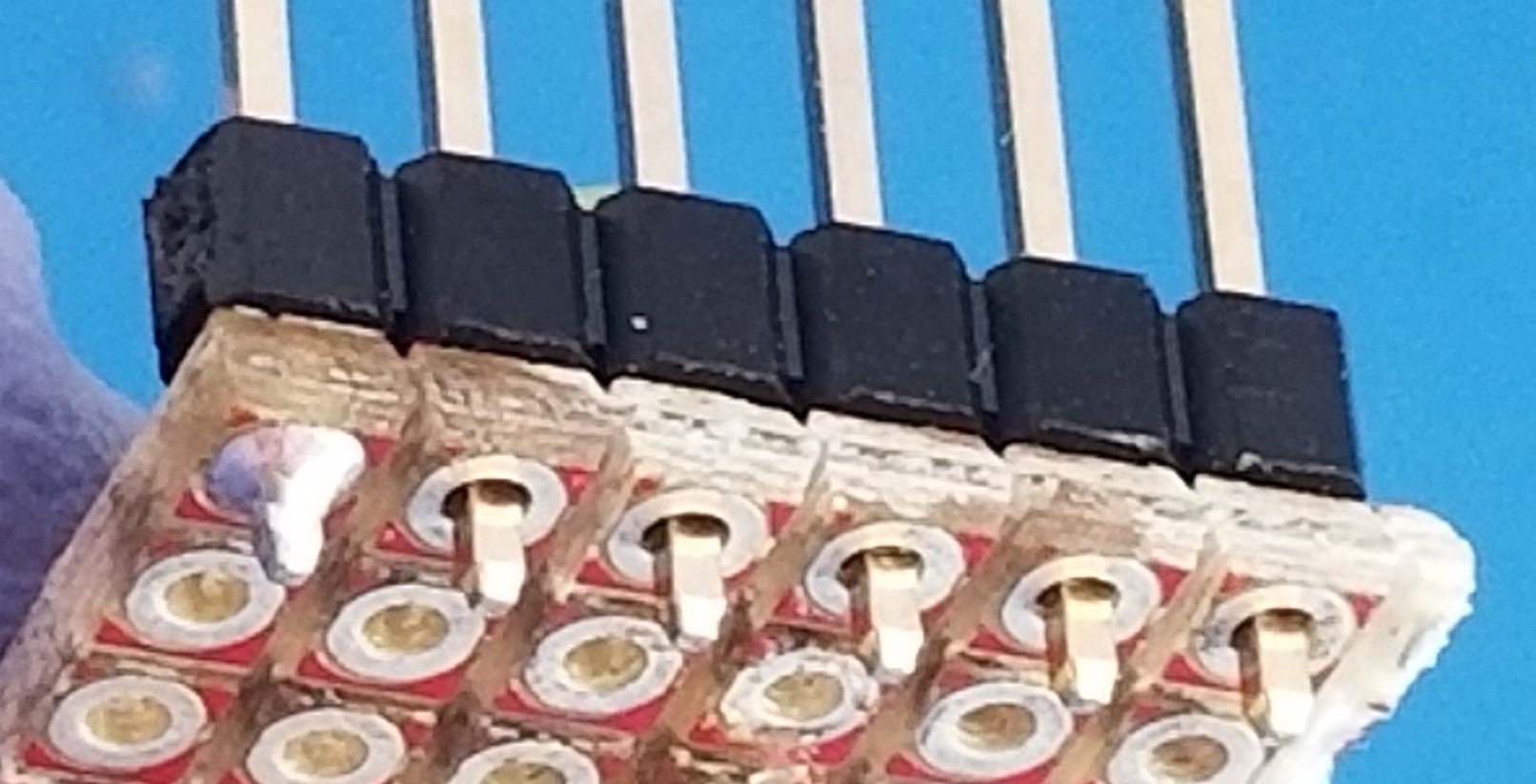
Then continue to solder the rest of the pins like normal and come back to the first solder joint to re-melt and add more solder to fully fill the solder joint.
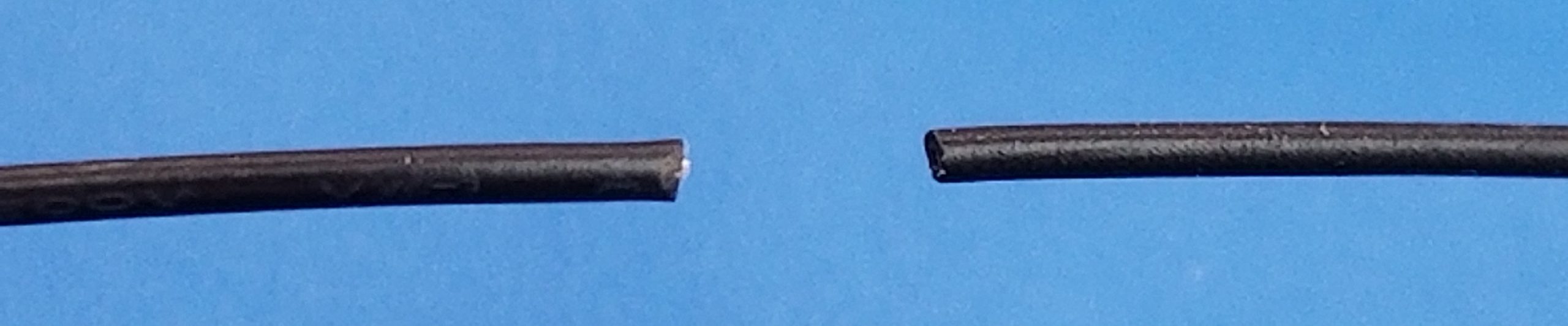
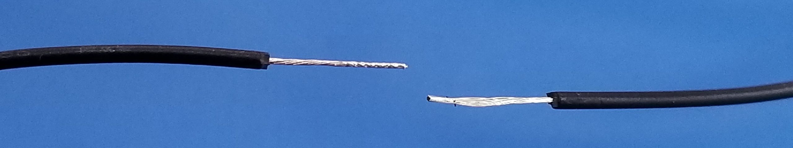
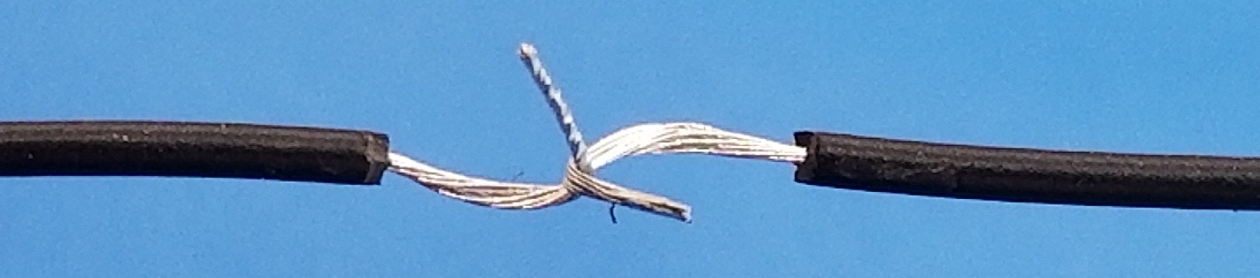
Wires can be spliced together by stripping the ends off, forming “hooks” with both wire ends, and twisting those hooks together, and soldering them together. Depending on the environment of those wires, you may want to add some insulation like electrical tape to wrap the exposed wires or placing some heat shrink insulation onto one of the wires before attaching them together. Be careful because when a solder joint starts to collect a large amount of mass it can become increasingly difficult to heat the mass up to melting point, so it’s better to get the core of the spice covered in solder quickly without adding unnecessary solder.

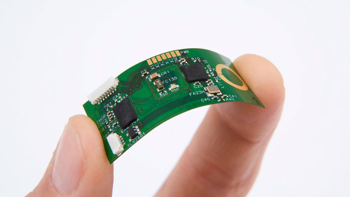
Through-hole components are easily handled and are great for experimentation, but a good final product is best suited in its smallest and most streamlined configuration. This is achieved with the use of tiny surface-mount components, but their very tiny mass and footprint can make soldering using an iron a clumsy and failure-prone experience if care is not taken.

If you simply try to place a surface mount resistor and try to solder one side then the other, you’ll find the molten solder pulls the resistor vertically, resembling a “tombstone“. To approach this, a small amount of solder can be placed on one of the component PCB solder pads, then using non-ferrous tweezers, hold the component down onto the solder pad while heating with the iron. Remove the iron and let the solder solidify while holding the component in place and then easily solder the other side. Note that these components need very little amounts of solder compared to through-hole, so a small amount of solder on the tip of the iron can often be plenty to attach one of these small components pins.
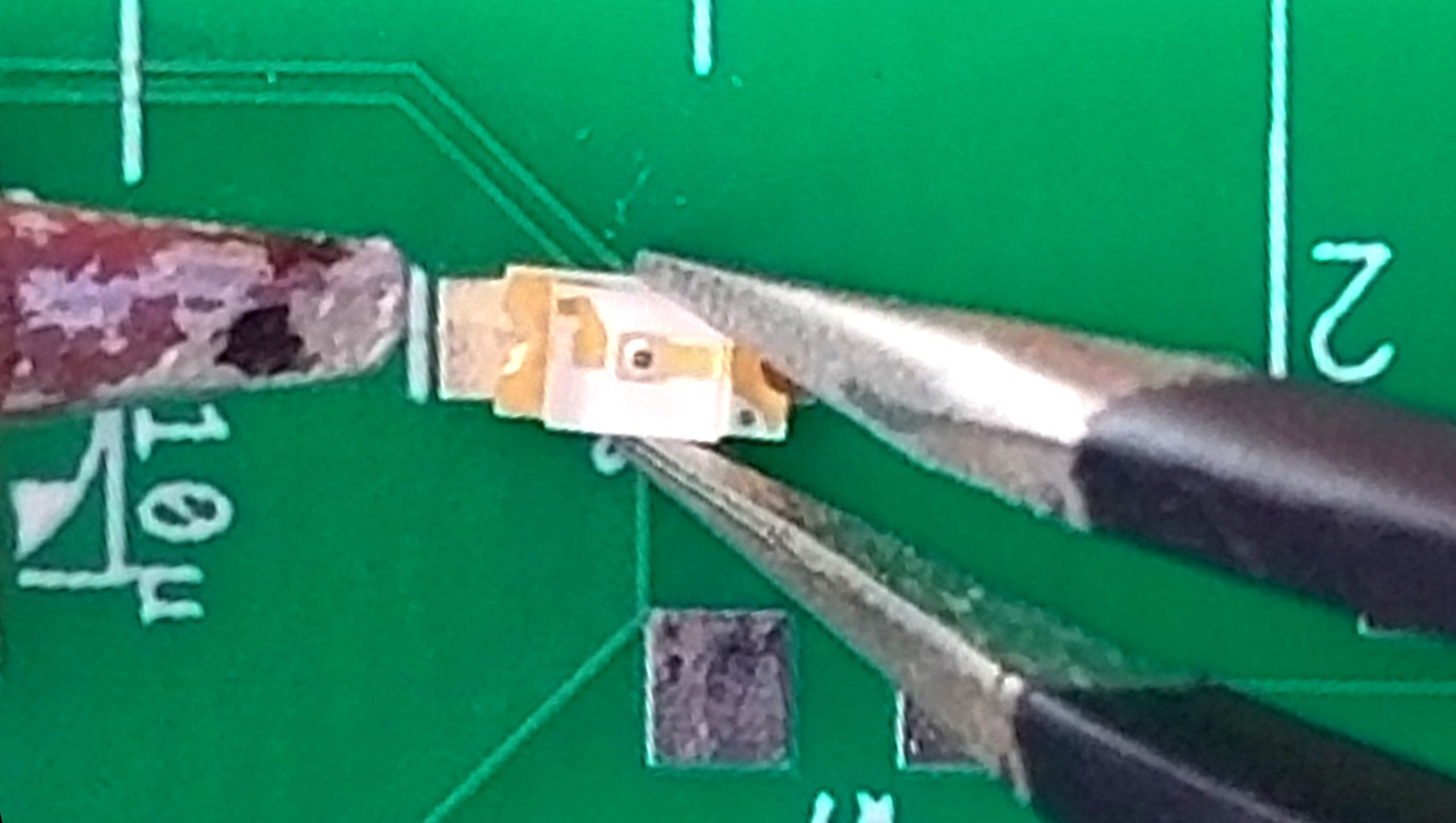
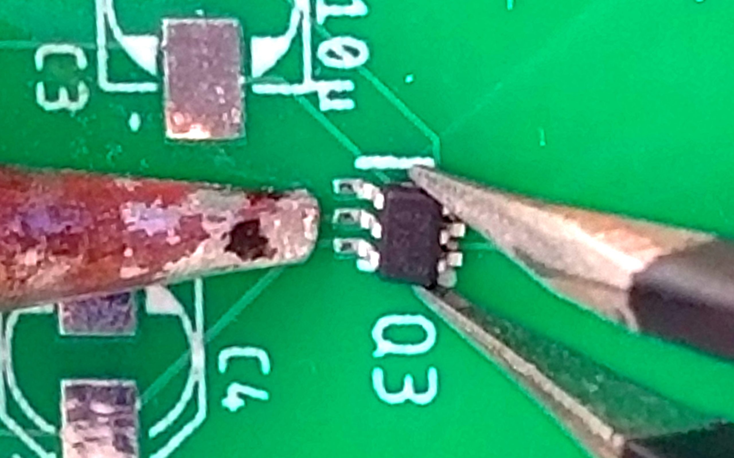
Surface mount ICs can be even more delicate because the part must be more carefully aligned with the smaller and closer pins being more easily prone to having solder bridges that connect two adjacent wires that shouldn’t be connected. With sufficiently small components, often the amount of solder used to “tin” the tip of an iron at the beginning of a soldering session can be enough to keep one or more of these tiny surface mount connections. So a nice and easy way to approach SMD ICs is to apply some flux paste to the solder pads and add a small amount of solder to the tip of the iron. Hold the IC in alignment using tweezers, and in one fluid motion sweep the blob of solder across the IC contacts. If solder bridges have been formed, clean the iron tip and sweep across the contacts again with a clean iron tip and the iron will take some of the extra solder.
Cleaning
Generally, you want to clean your PCBs after soldering, if a corrosive flux was used, leaving the PCB covered in that flux can cause corrosion over time. This can be prevented by using “no-clean” fluxes and solders, or by using solvents like isopropyl alcohol or acetone, or by using deionized water cleaning systems if using fluxes that are water-soluble.
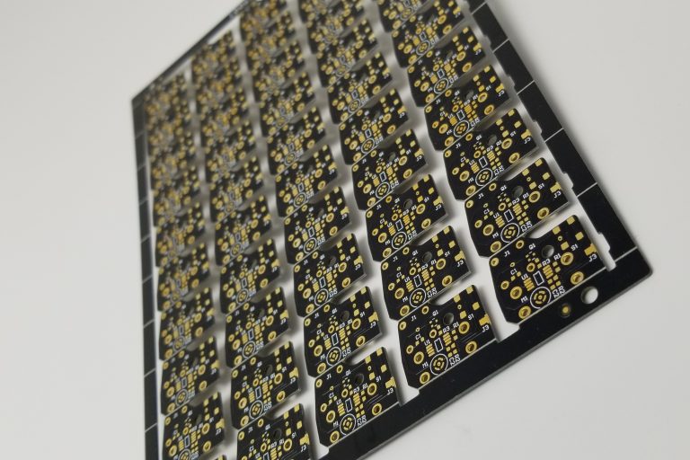
Soldering one PCB can be great practice, but 1000 can be a chore. Get your quote from OnBoard Circuits for a bulk order here!