Every now and then we get requests from some customers to repair some arbitrary circuit board and we must then switch our hats from design or assembly to a diagnosis and treatment-oriented one. Depending on the circumstances, solutions can be quick and easy, but sometimes there are more complex forces at play that make a repair more tricky to completely fix. One thing is for sure, you get to see some interesting devices and failure conditions when exploring PCB repair.
Discovery
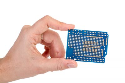
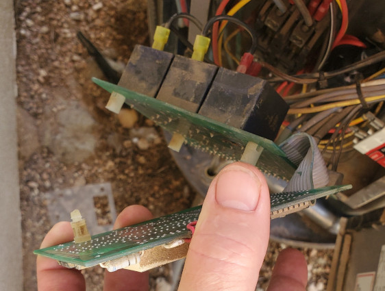
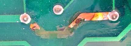
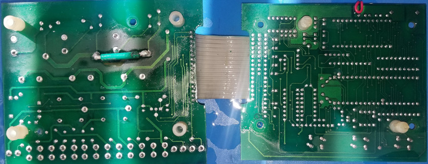
Recently we had a customer come in with a pool heat pump control assembly with these pictures showing a thick power PCB trace that appears to have heated up to the point of cooking right off the board. The customer wants this trace reconnected and hopes to find out whether or not the relay near the burned trace is damaged, requiring further repairs. As we take the assembly into possession, we also discover that the interface wires between the two boards have snapped in a couple of places likely due to heat and sunlight making the wires more brittle over time and then handling the boards and wires.
Disassembly
Simple enough, reconnect the lost trace, determine if the relay is ok, and fix the wires. The assembly consists of a display/control module that has the display and buttons for user input and a relay board controlled by the control module through some thin interface wire. The whole assembly was covered in a “gunky” dust characteristic of long-term exposure to the elements and now had carbon deposits from the burned trace, so a good wash was in order. After a quick scrub using 91% isopropyl alcohol, we desoldered the wires that had snapped off and clipped off the copper trace that had been pulled from the PCB, and used a hot air rework station with a desoldering pump to remove one of the three bulky relays on this board that was closest to the burn.
Inquiry
A quick search for the relay part number “AZ2100-1A-12DE” shows us the internal circuit of the part and how it should appear when measured with a multimeter. When measured, the relay coil was within 10% of what the datasheet specified it should be, and when testing using its minimum control voltage of 9 Volts, its contact firmly and consistently slammed shut completing its control circuit. The relay is perfectly fine. After some quick examination of the rest of the relay circuit boards traces, we attach control signals directly to the board to test the remaining two relays in the circuit, just to be thorough. Again, the relays are in perfect health condition. This is both good news and bad news. The good news is that this board will require no additional repairs once the broken or removed elements are added back on. But the bad news is that something caused this burn, and the source does not appear to be on this board.
Some more research of the part numbers on the PCB brought us to a forum thread about what seems to be the same control assembly. This part seems to be the internals of a Viconics HP727 which the customer said that they also had to replace a capacitor that had gone bad. This forum thread describes a problem where one of the relays themselves is getting burned out and needing replacement and when they are replaced, the new relay burns out within a month. Luckily we don’t have a burned relay so this repair is cheaper and faster than needing to order a new part, but we certainly want to fix the source problem rather than apply a superficial fix. It appears from this thread and from the customer description that there is a somewhat consistent problem with the same electrolytic capacitor that is causing a power surge through the output of the relay.
Resolution
Unfortunately, we didn’t have the full assembly to be able to test while in operation so this is where we get off of this train. Weresolder the relay back to the PCB, add a thick wire to replace the burned trace, and resolder the wires that snapped off connecting the relay board to the control/display board. Given how similar the forum thread problem was to our customers describing the problem, we recommended a similar solution to theirs. It could be that the capacitor our customer replaced is under specced in its voltage tolerance. A solution could be to replace this capacitor with one that has a higher voltage tolerance with otherwise identical characteristics. For example, if our relay control circuit operates at 12V and interconnected capacitors are only rated to 13V, that wouldn’t be a problem if the voltage seen by those capacitors is always smooth and level 12V. But in the real world, sometimes power gets a little messy and you can see brief spikes. And if those spikes in this circuit take the capacitor voltage slightly over its rated voltage, it will start to degrade that capacitor. This degradation can cause the capacitor’s actual capacitance to change, causing it to not behave in the circuit the way that it should, allowing power surges to ripple through a circuit. These are also a kind of part that can go bad faster than other components requiring replacement in older equipment so this part could have simply gone bad due to age.
Upon presenting these findings to our customers they state that they also didn’t realize that these larger electrolytic capacitors are polarized and must be installed in a particular orientation otherwise they are prone to violent failure. Thankfully we were able to inform the customer how they can identify markings on a capacitor and circuit board to ensure it is connected properly. We were happy to help out by fixing that board and providing a little more information about that capacitor that our customer already had some troubles with and we hope that our assistance got them closer to a renewed pool heat pump that purrs like a kitten again.
Do you have a circuit board that is under the weather? See if we can help by contacting us here!