When it comes to electronics design and fabrication, we stand on the shoulders of giants. One of the ways that we benefit from those who came before us is we get to learn from the mistakes of others, and as any designer knows, there are innumerable amount of things that can go wrong with any particular design. Let’s take a look at some problems that can occur in PCB designs.
Clear labeling
Are you assembling your own product or outsourcing assembly? In either case, care must be taken to make component placement and values clear to whoever is assembling the final unit. Say you have several passive components that are all in an 0805 package, is it clear what footprints belong to resistors or capacitors? Maybe you know for sure where all of the components go and are planning on assembling yourself, but will you remember those details if you assemble 6 months later? Do yourself and anyone else assemble your products by using the silkscreen layer to clearly label your component type and polarity with markings large enough to be read by the human eye. This may not be a “functional” issue like accidental short circuits, but this is an easy step that can save a lot of headaches.
Missing layers
In an I.T. department, a very common solution is “turn it off and on again” or “make sure it’s plugged in.” In PCB fabrication, missing layers can be one of those problems you’d initially think is so obvious that no one would overlook a missing layer. But when you’ve spent long hours meticulously designing a circuit and carefully arranging the components, it can be easy to forget to draw a simple rectangle on the dimension layer to give your PCB an actual shape.
Incorrect/Mismatching Component Footprint
A quick search through Digikey can show that any component type has immense variety in size and shape. It can be easy to confuse one component for another and accidentally use the wrong package size for a given component. Always double-check the datasheet for your component to verify your design footprints match the footprint described in the part documentation
Insufficient trace width for high current paths
Sometimes all you need is any old wire to connect two points. But sometimes you’re driving more hefty loads, and that can generate some heat. Maybe the designer anticipates that this requires a thicker trace and just picks some thicker size, but how do you know it’s enough? Passing too much current through a trace can burn and sever the connection or worse, so always make sure that your traces are thick enough for the power passing through. Using a trace width calculator or reference table can help with this.
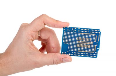
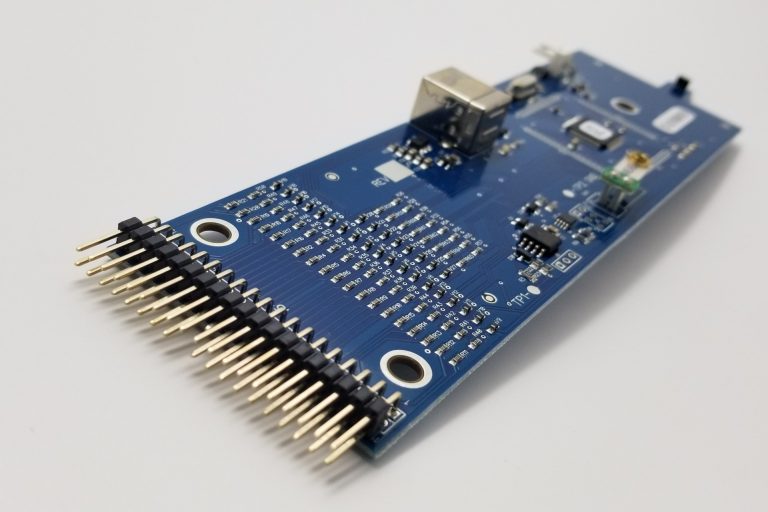
Insufficient solder pad size for pins
This is another issue that might not create an electrical issue, but it certainly can make the product unnecessarily difficult to assemble and increase the probability of problems arising while soldering. Sometimes a designer just wants to put some through-hole pins in their design, and it might seem simple enough until they get the PCB in hand and realize that the solder pads might be so small that they wish their soldering iron tip was thinner and pointier. Give yourself a little extra room and increase your solder pad size to accommodate a wider variety of iron tips.
Trace and pour isolation
Humans are imperfect, and the same can be said for our machines. Just because a design looks great with traces and copper pours tightly packed together doesn’t mean that your favorite PCB fabricator is capable of reliably creating such tiny features. Make sure to set your trace and copper pour isolation high enough to reduce the likelihood of PCBs coming out with connections where there shouldn’t be.
Avoid EMI (Electro-Magnetic Interference)
High-speed or high-frequency signals are great, but sometimes sharp geometry in PCB copper pours can unintentionally have the effect of an antenna, causing the end product to radiate electro-magnetic energy into the surrounding area. Avoid this by keeping your copper pours in more rounded blob shapes and avoiding longer runs of copper. Especially avoid leaving long runs of copper unterminated since this creates a tiny antenna. If the design is going to use multiple copper layers, consider designating one of the layers as a ground plane.
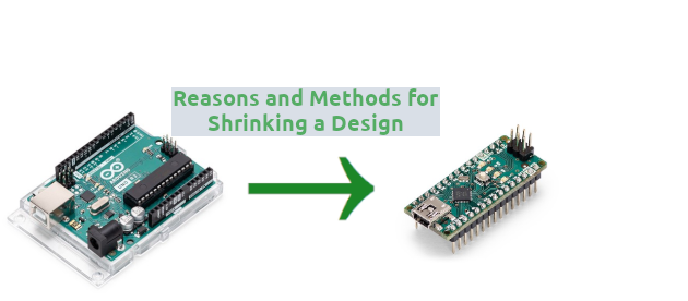
Physical conflict with enclosure
It can be easy to dedicate hours, days, or weeks to making and fine-tuning a PCB design, only to forget that often these are destined to fit inside an enclosure of some kind. Make sure that the PCB physical form will fit inside its intended box, and take care to strategically place drill holes in the design to accommodate mounting screws to fasten the PCB to its enclosure.
Have an innovative design for a product?
Take the next step and get a quote for a prototype or bulk run here!