Common Causes of PCB Failures (and How to Prevent Them)
With PCBs being central to nearly every electronic device, even a small PCB failure can cause big problems.
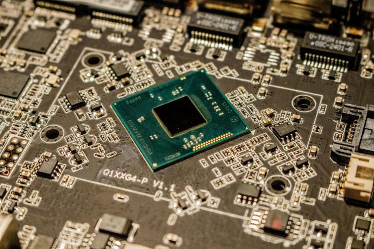
It’s nothing short of amazing how much of our modern world depends on printed circuit boards (PCBs). From your smartphone to your car, PCBs power the technology that runs our daily lives.
Here are just a few examples of common items that rely heavily on PCBs:
-
Consumer electronics – smartphones, televisions, speakers, alarms, computers
-
Automotive components – navigation systems, dashboard displays, sound systems, sensors
-
Medical devices – X-rays, imaging systems, surgical instruments, heart monitors
-
LED lighting systems – smart bulbs, display panels, and industrial lighting
-
Industrial equipment – machine controllers, motors, cutters, and automated production lines
That’s just the tip of the iceberg!
Although PCB failures are relatively infrequent, when they do occur, they can lead to costly repairs, delayed production schedules, and product recalls. Fortunately, understanding the root causes of PCB problems can help you prevent them before they happen.
In this article, we’ll explore the most common causes of PCB failures, how to spot the early warning signs, and what you can do to prevent them — with insights from the experts at OnBoard Circuits, a trusted U.S.-based PCB manufacturer and assembler.
1. Poor Soldering
Soldering is one of the most critical steps in the PCB assembly process. Even minor soldering errors can compromise the entire circuit’s performance, thus leading to PCB failure.
What Causes Poor Soldering?
-
Improper heating: If the soldering iron or reflow oven temperature isn’t properly controlled, it can result in “cold joints,” where solder doesn’t adhere fully to the pad or component lead.
-
Contamination: Moisture, dust, or oxidation on the board or components can prevent solder from bonding correctly.
-
Excessive or insufficient solder: Too much solder can create bridges between pads, while too little can result in weak joints.
How It Affects Performance
Poor soldering can lead to:
-
Intermittent or failed electrical connections
-
Short circuits or component burnout
-
Reduced long-term reliability of the PCB
How to Prevent It
-
Ensure proper soldering temperature profiles
-
Use high-quality flux and solder materials
-
Maintain clean work environments
-
Partner with a manufacturer that performs automated optical inspection (AOI) and X-ray inspection during assembly

2. Aging Components
Even the best PCBs have a lifespan. Over time, materials naturally degrade, and components wear out.
Why Components Age
-
Thermal stress: Repeated heating and cooling cycles cause solder joints to expand and contract, weakening connections.
-
Environmental factors: Humidity, dust, and oxidation corrode metal parts.
-
Electrical stress: Overvoltage or overcurrent can shorten component life.
Warning Signs of Aging PCBs
-
Unexpected circuit failures or voltage drops
-
Components that overheat during operation
-
Visible discoloration or corrosion
Prevention Tips
-
Use components rated for the expected thermal and electrical load
-
Store PCBs in moisture-protected environments
-
Perform preventive maintenance on critical systems
-
Replace outdated components before failure — you don’t always need to replace the entire board
👉 Tip: OnBoard Circuits helps clients source up-to-date components and offers advice on replacements for obsolete parts, saving you from full redesign costs. This could help mitigate PCB failures.
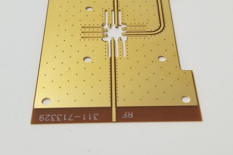
3. Missing or Damaged Solder Mask
The solder mask is the green (or sometimes red, blue, or black) protective layer on a PCB. It’s not just for aesthetics — it plays a vital functional role.
Why Solder Mask Matters
-
Prevents corrosion: It shields copper traces from oxidation and environmental exposure.
-
Prevents bridging: It keeps solder confined to its intended pads, preventing unwanted connections between traces.
-
Provides insulation: It protects the board from short circuits and electrical arcing.
What Happens When It’s Missing
When a PCB has missing or damaged solder mask areas, copper becomes exposed. This can lead to:
-
Solder bridging during reflow
-
Corrosion and short circuits over time
-
Reduced durability under humidity or temperature stress
Prevention Tips
-
Ensure mask application is uniform and defect-free during manufacturing
-
Inspect boards with automated solder mask alignment checks
-
Avoid manual rework that could peel or damage the solder mask layer
4. Ignoring DFM (Design for Manufacturability)
Design for Manufacturability (DFM) is a critical step that ensures your PCB can be produced efficiently, reliably, and without costly errors. Skipping DFM checks is one of the most common — and expensive — mistakes designers make that can lead to PCB failure.
Why DFM Is So Important
A good DFM review evaluates your Gerber files, spacing, trace widths, via placement, and other layout factors to catch potential manufacturing issues before production.
If DFM isn’t performed:
-
Components may not fit properly during assembly
-
Traces could be too close, causing shorts or yield issues
-
Boards may fail during testing, requiring redesign and re-fabrication
How to Avoid This Costly Mistake
-
Always include DFM review as part of your pre-production checklist
-
Collaborate with your PCB fabricator early in the design phase
-
Use design tools that incorporate DFM rules (like Altium or KiCad with manufacturer profiles)
👉 Pro Tip: PCBs can be designed using an array of PCB design software such as KiCad, Altium or CircuitMaker, among many other options. Submit your files early. Pre-production review can prevent delays and costly PCB failure.
5. Slivers on the PCB
During the etching or solder mask process, slivers—tiny strips of copper or mask material—can form. Though small, they can cause big trouble.
How Slivers Form
-
Etching defects: Over-etched or under-etched copper traces can create loose or narrow pieces of material.
-
Design geometry: Very thin copper features or sharp corners in the design increase the risk of slivers.
-
Mechanical cutting: When routing or punching the board outline, poorly supported edges can peel back small pieces of copper.
The Consequences
-
Floating slivers can detach and short out other parts of the circuit
-
Slivers can create uneven surfaces, affecting solder adhesion
-
They can contaminate the plating or solder baths, affecting other boards in the batch
How to Prevent It
-
Use manufacturer-recommended minimum copper width and spacing
-
Avoid sharp interior corners in PCB layouts
-
Inspect boards after etching and before plating
Other Common Causes of PCB Failures
While the above five issues are the most frequent, several other factors can also lead to PCB malfunctions:
-
Electrostatic discharge (ESD): Improper handling during assembly can damage sensitive ICs.
-
Thermal cycling: Repeated exposure to extreme temperature changes can delaminate layers.
-
Moisture intrusion: Absorbed moisture during storage can cause “popcorning” during reflow.
-
Contaminants: Dust, oil, or residue from cleaning solvents can create surface leakage paths.
Each of these factors underscores why manufacturing precision and environmental control are so important for PCB reliability.
How to Prevent PCB Failures Altogether
The best way to reduce PCB problems is to partner with an experienced, quality-focused manufacturer who understands every phase of production — from layout review to final assembly testing.
At OnBoard Circuits, we go beyond just fabrication:
-
Comprehensive DFM review before production
-
Precision PCB fabrication using high-quality FR4 and specialty materials
-
Turn-key PCB assembly services with strict quality control
-
Automated testing and inspection (AOI, flying probe, and functional testing)
Our team ensures every board that leaves our facility is tested, reliable, and ready for integration into your final product.
Conclusion: Partner with OnBoard Circuits for Reliable, High-Quality PCBs
The creation of a printed circuit board is a complex, multi-step process. From design validation to assembly, every detail matters. When something goes wrong — whether it’s a missing solder mask, poor soldering, or lack of DFM review — the consequences can be costly.
By working with a trusted, experienced partner like OnBoard Circuits, Inc., you ensure your boards are manufactured to the highest standards of quality, performance, and reliability.
From prototype to full production, our engineers oversee every phase — layer count, materials, surface finish, and assembly — to guarantee consistent results that meet your technical and budget requirements.
Need a Printed Circuit Board?
Get in touch with us today for a cost-optimized, high-quality PCB solution.
👉 Request a Quote from OnBoard Circuits